Control Servos, Relays, LEDs, Motors, and More Over Long Distances
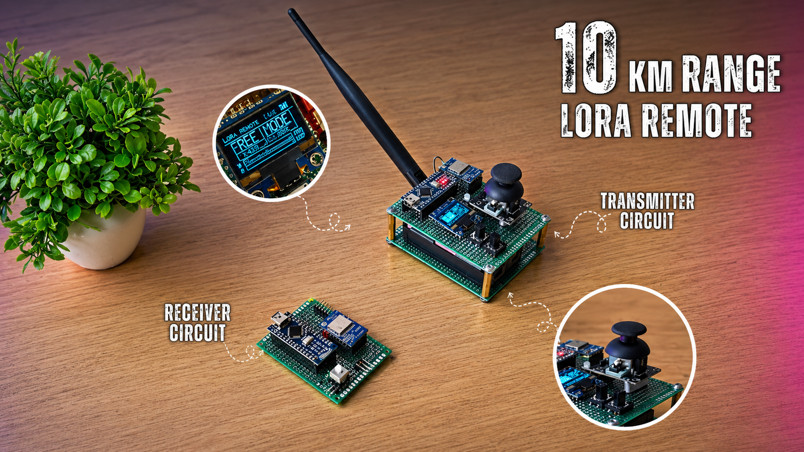
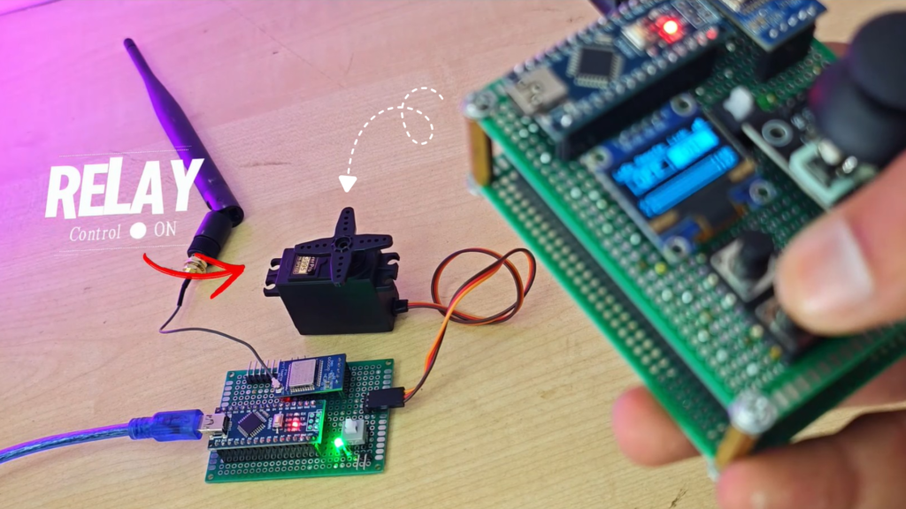
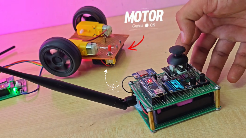
Long-range wireless communication has become one of the most useful technologies for robotics, automation, agriculture, and IoT projects. In this project, we built a fully customizable wireless remote control system using the REYAX RYLR993 Lite LoRa Module and Arduino Nano. Unlike ordinary RF remotes, this controller allows you to switch between PWM and Digital outputs directly from the transmitter menu, making it suitable for controlling everything from servo motors to relays without changing the hardware or firmware.
Why I Built This (and why you might)
This project was developed to create a long-range, reliable, and customizable wireless remote controller using the REYAX RYLR993 Lite LoRa Module and Arduino Nano. Unlike traditional RF remotes, it features a built-in OLED settings menu that lets users switch between PWM and Digital outputs, adjust joystick settings, and configure button functions without modifying the code. Its long-range communication, low power consumption, and flexible design make it an ideal solution for robotics, home automation, industrial control, RC vehicles, and IoT applications.
Parts List (BOM)
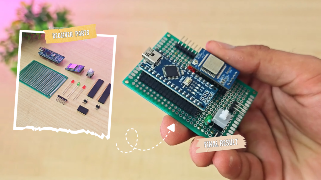
Receiver
- 1x Arduino Nano
- 1x RYLY993_Lite Module
- 2x Push Button
- Zero PCB
- 1x 0.96 Inch Oled
- On/Off Button
- 1x Joystick Module
- 2x Strip Female Header
- 7.4v Battery
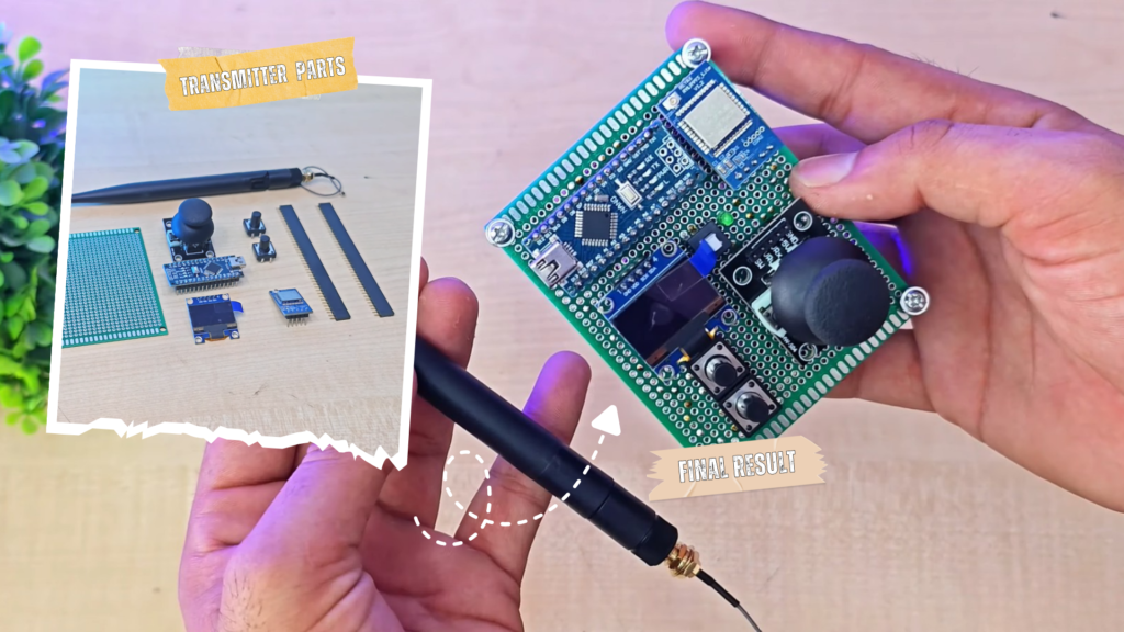
Transmitter
- 1x Arduino Nano
- 1x RYLY993_Lite Module
- Zero PCB
- On/Off Button
- 3x Indicator Led
- 2x Strip Female Header
- 7.4v Battery
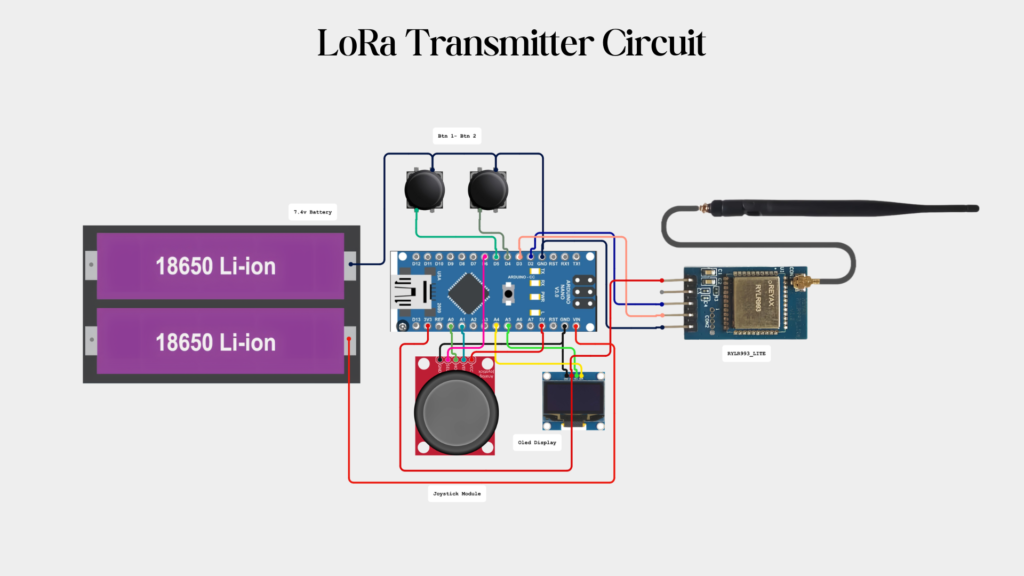
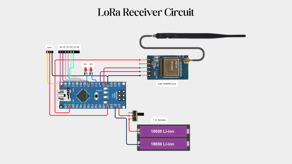
Connection Diagram
Step-by-Step Build Guide
Step 1 — Setup LoRa AT Commands
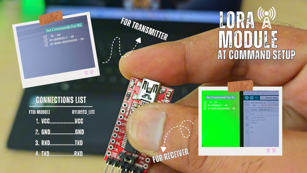
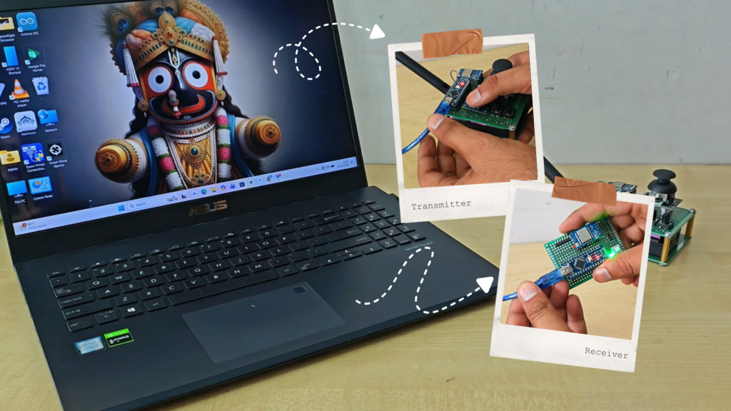
Before uploading the Arduino sketches, both REYAX RYLR993 Lite LoRa modules must be configured using AT Commands. Connect the LoRa module to the Arduino Nano (or USB-to-TTL converter) and open the Arduino IDE Serial Monitor.
1.Important: Make Connections First:
- FTDI TX → Module RX
- FTDI RX → Module TX
- FTDI Vcc → Module Vcc
- FTDI Gnd → Module Gnd
2. Serial Monitor Settings
- Baud Rate: 115200
- Line Ending: Both NL & CR
3. For Transmittter – Use The following AT Commands
- AT – OK
- AT+ADDRESS=1 – OK
- AT+BAND=865000000
3. For Receiver – Use The following AT Commands
- AT – OK
- AT+ADDRESS=2 – OK
- AT+BAND=865000000
Step 6 — Configure the Transmitter Using the OLED Settings Menu
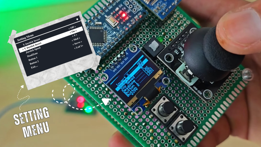
The transmitter features a built-in OLED Settings Menu that allows you to customize its operation directly from the controller. You can change button functions, adjust output settings, and save your preferences without modifying or uploading the Arduino code again.
- Open the Settings Menu
- Turn on the transmitter.
- Press and hold the Joystick Button for approximately 2 seconds.
- The Settings Menu will appear on the OLED display.
- Navigate Through the Menu. Use the joystick to move through the available options:
- Move Joystick Up → Scroll to the previous menu item.
- Move Joystick Down → Scroll to the next menu item.
- Move Joystick Left → Decrease or change the selected value.
- Move Joystick Right → Increase or change the selected value.
- Short Press the Joystick Button → Select, confirm, or save the highlighted option.
- Long Press the Joystick Button → Exit the Settings Menu and return to the main screen.
- Cusuomize the Controller. The OLED menu allows you to quickly configure the transmitter for different applications. You can:
- Assign a function to Button 1.
- Assign a function to Button 2.
- Select the desired Output Mode.
- Modify available controller settings.
- Save your configuration for future use.
- Save and Exit. After making the required changes:
- Press the Joystick Button to save the selected setting.
- Repeat the process for any additional settings you want to change.
- Press and hold the Joystick Button to exit the menu and return to the main operating screen.
OLED Display User Interface
The transmitter features a 1.3-inch OLED display that provides a simple and intuitive user interface. It allows you to monitor the controller status, view live control values, and configure settings directly from the transmitter. The main screen displays:
- Joystick X-axis value
- Joystick Y-axis value
- Button 1 status
- Button 2 status
- Connection/Transmission status (if enabled)
- Battery or power indicator (if available in your firmware)
- The interface updates in real time, allowing you to see the changes as you move the joystick or press the buttons.
Settings Menu Interface
The OLED also includes a dedicated Settings Menu for configuring the transmitter. Inside the menu, you can:
View all available configuration options.
- Navigate using the joystick.
- Change output modes for Button 1 and Button 2.
- Adjust controller parameters.
- Save settings directly from the display.
- Exit the menu and return to the main screen.
Download Project Files